A nice aspect of the Columbia graduate student experience is that the course projects are meant to tie into student research - this model falls apart only slightly when students take courses out of a desire for breadth or out of interest. My power electronics course project, as a result, is an independent labor of love. Despite my novice understanding of the material, I found the design problem very interesting and believe I created a viable product! I wanted to showcase some of the design here, and I'll try to keep the math to a minimum. For more technical details, I'll be uploading a report in the "Projects" tab.
It's important first to understand, on a basic level, how cochlear implants work. All commercially available implants consist of two devices: a receiver and a transmitter. The receiver is the "implanted" part of the implant - it contains an electrode array which stimulates the auditory nerve (from inside the cochlea) and some processing circuitry that lies right beneath the skin above the user's ear. The transmitter sits above the ear, and consists of a microphone to pick up sound, some processing circuitry, and a module for sending power and the audio signal to the implanted receiver.

There are a few issues for user's of cochlear implants as a result of this model. The largest is that the device is indiscreet - this opens people up to potential social stigmas as a result of being deaf, despite their implants allowing them to hear quite well. The solution to this problem would require a fully implanted device, which need not receive wireless power from an external transmitter.
Fully implanted cochlear implants are a hot area of research at the moment, and while they are not yet commercially viable, there is strong commercial and scientific interest in their development. One feature of a fully implanted system is that it must, necessarily, use very little power - whereas conventional implants draw about 20-40 mW of power, proposed fully implanted devices use only about 1 mW! This is due to aggressive power optimizations of the processing circuitry, as well as the fact that no loss is incurred by a wireless transfer of power in a fully implanted device.
This power-optimized technology could, in fact, be leveraged in conventional cochlear implants as well. While wireless power transmission will always be lossy, lower power constraints on processing circuitry could greatly increase the battery life of the transmitter.
Most cochlear implant transmitters use either rechargeable batteries with battery lives of 24-48 hours, or one-use batteries. The former is, on face value, more desirable due to the cost over time of buying one-use batteries. However, batteries do become less efficient the more they are recharged (as any cell phone owner knows), and replacing an entire device rather than a battery is far less convenient.
With a lower-power system, rechargeable batteries are charged less often and thus burden the user less and remain efficient for longer. One-use batteries, similarly, must be bought less often and thus save the user money. It is an all-around win for user experience, but requires a higher up-front cost.
My idea was to take this one step further - with a low-power system, could a hybrid power system be used to achieve near-infinite battery life? Devices like calculators, which draw very low power, are able to maintain power for arbitrarily long without ever needing to be charged or replaced by the user. Whether or not this is feasible could be determined through the construction of a relatively simple prototype designed to simulate only the power aspects of the device.
As can be seen in the image above, the transmitter rests above the users hair in most cases and is thereby exposed to sunlight constantly. Solar power seemed to be the best choice, as solar cells are easily available in compact and even flexible form factors.

With solar power chosen, we can consider a small block diagram such as that shown above. Here, TX means transmitter and RX means receiver. The loads on either side,as well as the modulator, can be seen as devices which simply draw power, and are not actually built into the prototype.
The devices of interest here are the resonators (through which power is wirelessly transferred) and the photovoltaic power supply.
Wireless power transfer works through Faraday's law and mutual inductance. In short, an AC current through an inductor generates a changing magnetic field in the space around the inductor. Similarly, a nearby inductor which exists in this oscillating magnetic field will have a current through it induced. The strength of the magnetic field at this second inductor will depend on the distance between the two inductors, as well as the magnetic properties of the material between them.
The inductor size cannot be too large for our problem, both for aesthetic reasons and because the inductor must fit in an individual's skull! However, larger inductors lead to more efficient power transfer. The distance between the inductors and the material between the inductors is determined by the user's skin - in this region of the head, the skin is a thin layer about 4-10 mm thick, and skin has similar magnetic properties to air.
A resonator is a simple device, consisting of only an inductor and a capacitor. Depending on the inductance and capacitance, the resonator will "resonate" at a given "resonant frequency". That is to say that power and audio signal must be both transmitted and received within a small band of frequencies around the resonant frequency of these devices.
People familiar with communications theory will realize that, for one, a bandwidth of at least twice the audible range of frequencies is required for optimal power transmission, and also that ASK modulation requires "infinite" bandwidth. On the other hand, resonators are most efficient at low bandwidths, where only the resonant frequency transmits efficiently. Much like the inductor size problem, this is a fundamental problem in cochlear implant design.
For a laboratory prototype to be easily constructed I picked a relatively low carrier frequency (5 MHz) and built the resonators with discrete inductors and capacitors on a breadboard. Breadboards have awful parasitic profiles, but it is of little consequence as with a large number of components and a function generator, correct values despite parasitics were easily found.

With this simple circuit I was able to gain an understanding of the distance- and bandwidth-dependence of the circuit. In contemporary cochlear implants, ~40% efficiency is expected from these wireless power links. I found that at very low distances (5 mm or so) I could achieve 50-60% efficiency even with these small inductors. However, simply doubling that distance gave much worse results - only 10% efficiency. This speaks to the delicate nature of wireless power transfer.
The bandwidth was found to be close to 1 MHz, which is about the bandwidth of the average commercially available device. The bandwidth is actually dependent on the series resistance of the resonator - something we only have in our circuit as a result of parasitics. The bandwidth/power tradeoff could be manipulated through small series resistances in a more controlled prototype (on a PCB for example).
For an oscillator, I used a TTL 5 MHz oscillator which is meant to have a power supply of over 3 V. Despite this, what the manufacturers don't tell you is taht it works jut fine at any voltage above ~1.3 V, so I was able to use it with the AAA rechargeable batteries i was using for this project. I chose a squarewave oscillator because they're incredibly cheap, but they are less efficient than a sine wave oscillator for this application.
So with the wireless power module working, I moved on to the photovoltaics (the more interesting part, in my opinion). Charging a battery with a solar cell requires a few checks to make sure nothing breaks, and also that power is nowhere wasted. First, current should never flow into the solar cell - the cell is meant to charge the battery, and there is no use in "charging" the solar cell! Second, current from the battery should only be able to flow through the device, and NOT through the power circuitry. That is, no battery power should be wasted on charging the battery. Lastly, there should be a protection on the battery overcharging - a bettery rated for 1.5 V may be able to charge up to 3 V, but this could have physically unsafe consequences or could ruin the battery permanently.

The circuit above prevents current flow in "the wrong direction" using two diodes, and prevents overcharging with a Zener diode. To see how it prevents overcharge, consider the case in which the battery is not overcharged - the Zener diode acts as an open circuit, the transistor is off and the regulator provides whatever voltage it is set to provide. Once the battery charges enough to reach reverse conduction in the Zener diode, the transistor turns on, shorting the adjust pin on the regulator to ground and stopping the battery from charging. In low-voltage applications such as this one, we need to modify this circuit, as reverse conduction will never be reached for any given Zener diode at only 1.5 V.
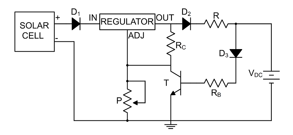
Using the circuit above, the diode drop and base-emitter voltage of the BJT will activate at 1.4V - a fine overcharge voltage for a 1.3 V hearing aid battery.
This circuit was built with a small solar cell and attached to the oscillator and resonators, show below:

The final implementation showed that in direct sunlight, a solar cell can completely power a low power budget implant, and continue to charge the onboard battery at the same time. At worst, the solar cell introduces a small amount of surface area to the external circuitry.
The breadboard design is, of course, too large as we are using discrete components. A small PCB was designed in KiCad - only 20mmx30mm! This shows that such a design could easily be implemented with a low-power implant.

So I was able to design and prototype a viable hybrid-powered device that greatly improves (best-case infinitely improves) the battery life of cochlear implants leveraging new low power budgets from fully implantable devices! Will we see such a hybrid device implemented before we see fully implanted devices on the market? I would hope so!
Again, if you are interested in the technical side, there's a report elsewhere on this website which covers past literature and some more detailed results. Stay tuned for other final project updates - I am also in the process of designing a laser scanning confocal microscope and a GPU-accelerated algorithm for OCT vibrometry!
Comments